Security Camera
The following rules will assist the designer to select the correct camera with the correct focal length and light tolerance capabilities for most simple installations:
1. Produce a plan view of the site showing the areas, which require CCTV coverage.
Mark the plan with approximate dimensions of buildings open areas and perimeters.
This will allow you to calculate the approximate numbers of cameras required and the relative mounting positions for internal and external cameras.
2. Select a suitable location for the control equipment. For reasons of compliance with Data protection Law and so that evidence cannot be easily removed from site the Video recording equipment should be installed within a locked room or placed within a locked cabinet.
3. When selecting suitable camera types consider the following:
· Is the camera inside or outside? External cameras require protection from the environment.
· What is the lighting conditions affecting the camera view. Is sufficient lighting for colour cameras?
· Consider the type of lighting to be used i.e. white halogen or Meta halide lighting for colour cameras.
· Would cameras that operate in very low light conditions be better such as Day Night cameras or would Monochrome or Night Vision cameras be more suitable
· If fixed cameras are to be used which lens will be most suitable for the size of image required on screen during live view and playback. If in doubt affordable cameras with built-in manual zoom lenses are now available. This enables the installer to adjust to the perfect picture during installation
· Is the camera low enough to be attached by vandals? Special cameras and cages are now available to protect cameras from damage. Home office guidlies for recognition of persons.
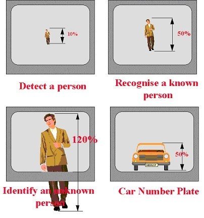
4. Consider the size and position of monitors. Are they best desk or wall mounted? Are they large enough to be seen without eyestrain?
5. Getting the video signals from the cameras to the recording equipment. Consider the type of cables to be used and how the cameras will be powered.
· Where will the cables be routed.
· Inside buildings? Outside buildings?
· Within underground ducting?
· What type of cable to use? This is normally determined by distance. 50 to 100 meters shotgun coaxial cable is best and most economical. Over this distance data cable CAT5e is good, especially if there are more than 8 cameras on the system. If distances are over 1000 Meters fibre optic cables may be more suitable.
6. Now the selection of suitable Digital Video Recording Equipment from the wide range available. Make your selection based on current and future requirements for numbers of cameras and audio feeds to be archived. How quickly you want to record (from 1 to 25 images per second per camera), the quality of the recorded image (size of image retreaved from the archive) and most importantly the size of archive storage (how long the video will be kept before it is overwritten. Location for the DVR (Digital Video Recorder), installed within a locked room or within a locked cabinet. DVR should be kept secure to comply with Data Protection Guidlines.
Finally, can the system be simply maintained and cleaned. CCTV system images are of no use as evedence if the lens was dirty or the recording system failed when an incident occures.
(1) Internal/External Synchronization
Synchronization is categorized in the following three types:
i) Internal synchronization
Timing of the camera is controlled by internal electronics for achieving self-synchronization..
2) External synchronization
The camera may be synchronized by means of an external synchronization signal. The timing of the unit is adapted in accordance tothis signal.
3) Power synchronization ( Line Lock )
When Powered by AC, the LL Synchronizes camera to power line zero crossing for achieving vertical synchronization.
( 2 ) Auto Gain Control (AGC)
This AGC function provides clear image in low light condition. This controls an amplifier that is used to boost the video signal when thelight dims so as to increase the camera’s sensitivity. In some bright environment, the amplifier may be overloaded and which may distort the video signal . So, it is necessary to monitor the signal level with AGC control circuit and AGC has to be switched off in case of necessity.
( 3 ) Back Light Compensation (BLC)
Generally speaking, the camera senses the whole area of the frame and measure the average light level. Working point of the AGC of the camera will be based on general testing of the whole environment and if there is a very bright background with very dim front image, back light compensation have to be switched on so that the camera can be adjusted to take the average on a specific zone forthe AGC working point. If the front image is put inside this zone, then the image quality can be much improved.

Lack of BLC function Unclear faces

Contain with BLC function Clear faces, but background over bright
( 4 )Wide Dynamic Range (WDR)
WideDynamicRange is concentrated in the solving problems in reversible light environment, backlight compensation (BLC) is the function of the camera itself to compensate for the shortcomings of the design. WideDynamicRange camera does not need backlight compensation ways to correct the picture. It is able to combine the advantages of the above two pictures.

Contain with WDR function à Clear faces and clear background.
( 5 ) Auto Electronic Shutter (AES)
AES - (Automatic Electronic Shutter) is used when a manual or fixed iris lens is fitted and the shutter speed will respond to the amount of light to keep the signal output at optimum level. AES allows to change the iris level automatically without using the auto iris lens.
When the electronic shutter is off, the shutter speed is set as 1/60sec for NTSC system and 1/50 sec for the PAL system. When the electronic shutter is on, the electronic shutter can be set in steps from 1/60sec to 1/10000secs for NTSC system and in steps from 1/50sec to 1/10000 secs for PAL system. When the shutter speed increases, the light passing through the len will decreases and thecamera sensitivity will be reduced.
However, when shooting fast moving objects, the increased speed can provide freezing effect for the object image, thus providingbetter resolution.
The AES should be switched off when an Auto Iris Lens is fitted.
( 6 ) Auto White Balance/ Auto Tracking balance(AWB/ATW)
White Balance allows the camera to adjust the tone according to the color temperature of the light source illuminating the subject. It allows the operator to see object as they appear during daylight. There are three white balance control modes, namely Auto trackingwhite balance (ATW),
Auto White Balance (AWB) and Manual White Balance to meet a wide range of operational conditions.
1) ATW functions by detecting white color in the scene at a color temperature from 2500 to 8000 Kelvin.
The color temperature is being monitored continuously and the white balance is set automatically by internal controller.
ATW is most suitable for viewing objects with changing color temperature and which can make the picture color looks more natural.

Auto Tracking White Balance - 5300 Kelvin.
2) AWB is a preset type function whereby white color in the scene is detected and white balance is automatically adjusted, then the setting status is stored. It automatically memorizes the adjusted white balance value every time the AWB button is turned on. ATB ismost suitable for environment with little change in light source.

Auto White Balance
3) Manual (R/B Gain) – It is used to adjust the red and blue color of the viewing image.
It allows adjusting red and blue gain manually according to user requirement.. With the manual white balance turned on, the auto whitebalance will be automatically turned off.

Manual (R/B Gain)
( 7 ) Auto Light Control/Electronic Light Control(ALC/ELC)
ALC (Auto Light Control)
Automatic Light Control (ALC) indicates the image sensor's ability to automatically adjust in diverse lighting conditions to yield the most vivid video image possible. It allows the auto-iris circuitry to either take bright spots more into consideration (peak), bringing out detailin bright areas, or less into consideration (average) bringing out detail in shadows.
For automatic brightness control in the ALC function, an auto iris lens with a voltage controlled aperture (DC) is necessary.

Without ALC function.

With ALC function
ELC (Electronic Light Control)
ELC compensates for moderate light changes in indoor applications without the use of expensive auto iris lenses.
A fixed iris lens or manual iris lens can be used. ELC allows the changing of shutter speeds up to 1/100,000 second. This allows forsharper images, even in limited lighting conditions.
( 8 ) Flickerless Mode
Flickerless mode is used for suppressing the flicker of light (illuminating the captured scene) produced depending upon the frequencyof the power source. In 50Hz area, the CCD exposure time is 1/50sec and if NTSC camera is used with working frequency of 60Hz, there will be flicker on the screen. Same will happen in using PAL camera in a 60Hz area. The shutter speed is fixed to 1/100 sec forthe 50 Hz area and 1/120 sec for the 60 Hz area to reduce the flicker of the fluorescent light.
Major characteristics of CCD
(1) Camera Format:
Camera format is a measure of the size of the imaging area . It refers to the diagonal size of the imaging area.
Common optical formats include 1” , 2/3”, 1/2”, 1/3”, 1/4” and 1/5”. The respective diagonal length are as follows:
1 “ - Width 12. 8 mm , Height 9.6mm , Diagonal length 16mm .
2/3” - Width 8.8mm , Height 6.6mm , Diagonal length 11mm .
1/2” - Width 6.4mm , Height 4.8mm , Diagonal length 8mm .
1/3” - Width 4.8mm , Height 3.6mm , Diagonal length 6mm .
1/4” - Width 3.2mm , Height 2.4mm , Diagonal length 4mm .
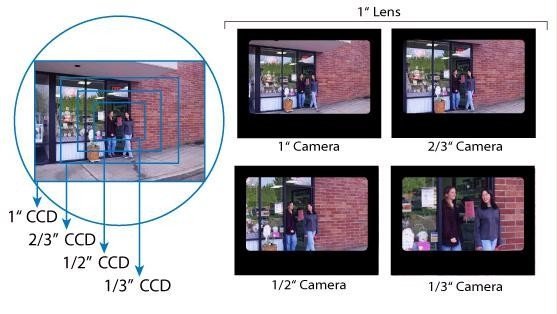
Generally speaking, a larger CCD chip will have bigger area and therefore bigger area for taking light, thus increasing the sensitivity. In dim light condition, this will improve the picture quality and make the picture looks more natural.
(2) CCD Pixels
Images are made up of millions of picture elements called pixels . Active picture elements are the actual number of light-sensitive elements within the camera imaging device. Active picture elements are expressed with a vertical and horizontal number. A camera specified with 768H by 494V has 768 rows of horizontal elements and 494 rows of vertical picture elements.
The quality of a digital image, referred to as resolution, depends on the number of pixels used to create the image. The more the pixels are, the higher the resolution of the resulting image
(3) Horizontal Resolution
Resolution is the ability of a camera to represent fine detail. The better theresolution, the more detail is perceivable to the observer. TV images are two dimensional, vertical and horizontal. Vertical resolution is measured by the number of alternate black and whitehorizontal lines that can be distinguished in the height of the camera image.
Horizontal resolution is measured by the number of alternate black and white vertical lines that can be distinguished in the width of thecamera image, multiplied by a correction factor (K factor) of 0.75 times to correct for the difference in the picture height to width ratio (3:4).
Vertical resolution is independent of system bandwidth it is often fixed for a given video standard (e.g. PAL or EIA). However, horizontal resolution remains variable and very much depends on to the quality of the transmission media (cables, etc.) and system bandwidth.
When "resolution" is discussed for camera comparison purposes it is generally presumed to be horizontal resolution.Horizontal resolution lies in the range from 320 to 500, expressed in TV Lines
4 ) Minimum Illumination
Minimum illumination is expressed in Lux. It is called sensitivity and refers to the minimum amount of light that will produce pictures.The lowerthe number, the more sensitive the camera is.
A camera requires 1.5 lux in order to capture a clear image. 0.1lux is equivalent to moonlight while 400 lux is equivalent to office lighting or a clear sunrise. The following are some typical light levels:
100000 Lux Sunny day
10000-100000 Lux Sunny day with some clouds
100-10000 Lux Overcast sky
100-1000 Lux Home/Office lighting
1-10 Lux Street lighting
0.1 Lux Full moon
0.01 Lux Young or Half moon
0.001 Lux Clear moonless night (starlight)
0.0001 Lux Dark cloudy moonless night (starlight)
CCD is categorized as:
Standard Class. Minimum resolution is 1-3Lux.
Moonlight Class. Minimum resolution is 0.1Lux.
Starlight Class Miniimum resolution is 0.0005-0.001Lux
Infrared LED Class. Minimum resolution is 0Lux with the use of IR LED
Standard Camera
Starlight Class Camera
Standard CCD view.

Starlight class camera
(5) Scanning System
Scanning system is categorized as PAL AND NTSC. PAL system (CCIR for B/W is adopted in China with 625 lines, 50 fields. NTSCsystem (EIA for B/W is adopted in Japan with 525 lines and 60 fields .)
(6) Power Supply
220V, 110 V and 24V is available for AC and 12V and 9V is available for DC supply.
(7) Signal to Noise (S/N) Ratio
Typical value for S/N ratio is 46dB. If the S/N ratio is over 50dB at zero AGC, this will give very accurate reproduction of the colors.
Even when the AGC is automatically activated, the pictures remain sharp. there will be slight noise but the image quality is acceptable.
If theS/N ratio is over 60dB, the image quality will be very good with very little noise.
( 8 ) Frames Per Second (FPS)
Frame rate, or frame frequency, is the measurement of the frequency (rate) at which an imaging device produces unique consecutive images called frames.
Frame rate is most often expressed in frames per second (fps).
General speaking, FPS greater than 16 will be considered to be coherent. The higher the frame rate, the higher the degree of fluency screen.
Universal video card can also reach 16-24 FPS. But for the highly-dynamic cameras, such as high-speed dome camera, the frame-rate which less than 24 per second, the screen will appear inconsistent, it is because the two are caused by different imaging principle.
What does ICR ( IR cut filter ) means?
IR Cut Filter (ICR):
When the scene illumination is lower than 2 Lux, the camera switches automatically from Color Mode to B/W Mode to catch clear image in the night time; when the illumination is higher than 8 Lux, the camera regains from B/W Mode to Color Mode. (Note: The 2 Lux and 8 Lux are just examples for your understanding. To know an exactly information, please kindly refer to the specification you’d care.)
Purpose of IR Cut Filter in Color Cameras:
An IR Filter, or IR Cut Filter, is a color filter blocking the infrared light.
There are several good reasons for using an IR-cut filter.
Using a color camera to achieve realistic colors in white light requires an IR-cut filter.
The color spectrum seen by the human eye is quite limited compared to the spectrum seen by a CCD camera.
Especially, in the near infrared region of the spectrum the difference in sensitivity is significant.
This is important to know since many light sources, including the sun, emit infrared light.
A CCD color camera in daylight without an IR-cut filter will therefore see a significant amount of infrared light resulting in strange colors.
Another reason for using an IR-cut filter is the limited color correction for many lenses.
It is difficult to design imaging optics covering both the visible spectrum and the near infrared spectrum at the same time.
Therefore, many lenses have different depth of focus for the visible and the infrared spectrum.
Anyway, the IR-cut filter cuts away a significant amount of the overall collected light and thereby affects the sensitivity in a negative way.
In general, color cameras are one factor less sensitive compared to monochrome (depending on the CCD chip).
This is primarily due to the IR-cut filter.
Main categorization of the Lens:
Categorized by len installation mount.
There are two common mounting styles for video camera lenses.
C-mount lenses have a distance of 17.5 mm betweenthe flange of a lens and the CCD imaging sensor ( called flange-back distance ),The C- amount are suitable for both C-mount and CS-mount cameras. CS-mount lenses have a flange-back distance of 12.5 mm and require a 5 mm adapter for use with C-mount cameras. Both C and CS mount use the same thread pattern of 1.00/32mm.
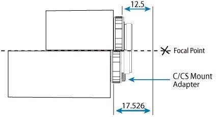
Categorized by CCD dimension:
Camera lens depends on the CCD dimension and should be used in harmony.
When the CCD is 1/2”,1/3”,1/4” , the lens will also be1/2”,1/3”,1/4” accordingly.
Categorized by Iris:
Manual Iris Lenses.
The iris in a lens is what controls how much light is allowed through.
A manual iris lens allows you to adjust the iris manually.
This is usually done when the camera is installed. if there are drastic changes in light levels, (eg sun shine), the picture could then be washed out because the iris is letting in too much light.
These lenses are better suited for indoor environment where lighting levels remainconstant.
Auto Iris Lenses.
These lenses have an electronic circuit inside, which controls the iris.
The lens usually has a 4-pin connector which connects to the camera, where it gets its power supply (9vDC) and its video signal.
The lenses electronics then analyses the video signal level and if there are changes to light conditions, the iris then adjusts accordingly to provide the best picture possible.
Auto iris lenses are most suitable for outdoor or entrance environment where light levels changes are drastic.
There are two types of auto iris lenses:
Video Drive.
With a video driven lens, the video signal is picked up from the AI connector, which is connected to the camera.
Because the lensadjust the iris based on the video signal, the lens is referred to as a video drive lens.
DC Drive.
DC driven lenses do not have the electronics for video processing, but rather only the motor that opens and closes the iris.
The whole processing process in a DC driven lens is done by the cameras AI electronic section.
A dc drive opens and closes the irisbased on the DC voltage being provided by the camera.
The DC drive lens relies on the camera to analyze the video signal.
Video drive lenses cannot be used with cameras that provide DC AI output, and DC drive lenses cannot be used with cameras that provide video AI output. They are not cross compatible!
Categorized by focal length/angle of view:
Focal Length
Focal length is the distance from the optical center of the lens to the image sensor plane.
Angle of View
To put focal length in perspective, the focal length in the human eye is approximately 17 mm.
This focal length gives an undistorted solid image angle of approximately 30 °. This is why an angle of about 30 °. is considered astandard angle of view.
The focal length determines the angle of view. The smaller the focal length, the bigger the angle of view and thus the viewing area. Thebigger the focal length, the smaller the angle of view.
Fixed Focal Lenses.
Fixed focal length lenses, as the name suggests, provide a fixed focal length, i.a. give one angle of view.
Normal " lens, Normal lens has an angle of view of 30 ° which is the same angle of view and perspective as seen by your eyes.
A lens with a focal length of 8mm on a 1/3" camera or a lens with a focal length of 12mm produces a field of view similar to the view producedby the human eye.
Wide Angle lens.
Any lens shorter in forcal length (eg 4mm) than normal is referred to as "wide angle",
Wide angle lenses has an angle of view of at least 90° and can offer a wide field of view for broad image captures.
Telephoto lens.
Any lens with longer focal length (eg16mm), is referred to as "telephoto". Telephoto Lenses has an angle of view of less than 20° narrow
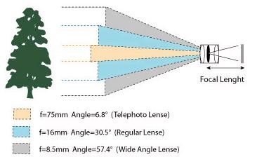
Different lens’ focus length.
Varifocal (Manual Zoom) Lenses:
This lens lie between the standard and wide angle lens.
The varifocal lens enables the user to change its focal length manually toproduce a zooming effect (narrowing the FOV)
Zoom or Motorized Lenses.
Zoom or motorized lenses are categorized into manual or motorized types.
Manual type is only used in research environment. In most of the surveillance environment, motorized type lens will be used together.
By remote controlling of the focus and the angle of view, motorized lens can offer wide zooming range, enabling the user to monitor wide zone and also able to zoom in to look into details ofthe viewing object.
Typical lens offer the flexibility for remote controlling of the focus and the angle of view.
This is critical for the supervision of high place,dangerous zone and . Typical lenses usually come in a range of 6x(8-48mm, F1.2), 8x(4.5-36mm), 10x(8-80mm), 12x(6-72mm), 20x(10-200mm).
Besides, optical zoom, digital zoom can also be offered as option.
Pinhole Lenses:
Pinhole lenses are small-diameter devices that are designed for insertion into tubes, holes, or other small areas.
Pinhole lenses with right-angle bends are called 90° pinholes.
Close Up Lenses:
Close-up lenses provide short focusing distances for digital photography or imaging.
Field of view samples:
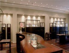


3.6mm Picture Area: 49' w x 35' h 6mm Picture Area: 29' w x 21' 8mm Picture Area: 22' w x 16' h


15mm Picture Area: 12' w x 9' h 55mm Picture Area: 3.25' w x 2.50' h
Optical Zoom / Digital Zoom:
Optical zoom lenses physically extend to magnify your subject.
A motor controls the lens movement. The greater the optical zoom, the more things can be taken far.
Digital zoom crops your image and magnifies the result of the cropping.
This magnification process is called interpolation. To make the cropped area bigger, digital zoom makes up, or interpolates, pixels to add to the image, which may give less than satisfactory results.
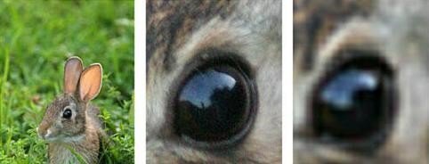
Original 10X Optical Zoom 10X digital Zoom
Copyrights onlinecamerashop.nl. Copy content without permission is forbidden!
To be continued!

